1. The Control Flows
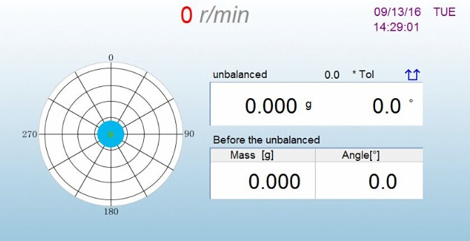
The controlling working process in automatic balancing machine system is mainly carried out to control the unbalanced measurement of the work piece and to correct the work piece. The operation of the clamp measurement, rotating clamp operation, and milling cutter are controlled by the PLC control, and they are slaves of the work piece rotation, feed by two stepper motors, which are responsible for driving the cutter forward and reverse, the work piece on and off. The control signal of the motor is given by the stepper motor control card. The process of the automatic balancing machine consists of two steps:
STEP 1: Unbalanced measurement - signal processing - to determine whether the work piece is qualified - then print the test report - otherwise proceed to STEP 2.
STEP 2: Fulfill the Control Program to remove weight - and turn to STEP 1 - to detect whether the work piece has been in standard. Rotation duration of the work piece is priority of this step since the rotating speed will affect the unbalance measurement accuracy and rotation duration. The duration determines the throughput of the whole line. During the acceleration of the rotation, the measurement signal is analyzed and the measurement signal is stabilized for several cycles, that is, the rotation is stopped and the other control actions are performed in parallel during the deceleration. In step 2, it is critical to establish a removal model, which determines the time and precision in removal process. The cooperation between the two steps (optimization) is also the control strategy that must be considered. In addition, the different parts of the dynamic balance before the calibration operation are always important in control process. The parallel arrangement of each step, optimization is to improve the system efficiency and energy savings.
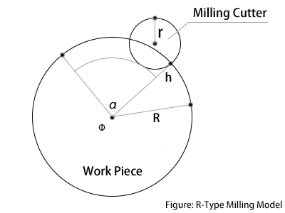
Due to the removal of large amount of imbalance, R-type milling is easier in positioning in the most widely used automatic balancing machine. Unbalance amount precision is usually defined as "g.mm/kg". Since the de-weighting is the distribution in the radial direction of the circle, there is a large bias in the method of multiplying the weight from the mass center to the rotor axis direction. Taking into account the influence of other factors on the rotor circumference (such as the irregularity of the trench surface or the roughness of the surface), the removed unbalanced amount cannot be in an arched block shape. Analysis of the removal model can be drawn, the milling can be divided according to the feed control method into different methods: to control milling depth or to control milling length. The actual applications can be selected according to the specific requirements of the work piece by the implementation of the corresponding software. If the first attempt does not make the work piece dynamic balance, the second or the third time will be more complex in balancing. So far our machines are restricted only one time removal can achieve rotor dynamic balance.


.png)
.png)

.png)
